24/12/2023
Design Time Baby!
I’ve been doing some research on the motor design and I think I have a good idea of what I’m going to do. I’ll try to explain the design process as I go.
Specification Considerations
I was a bit naive about the specifications of the motor in the first post of this series. Though, I still thing a 50-100 Watt motor would suffice for my use case. On the good side, I overestimated the cost. I think I can build it for much cheaper than I initially thought, which was around 100, nowIthinkIcanbuilditforaround30. This of course doesn’t include the cost of the battery but should include the cost of the ESC. I’ll come to the ESC later.
Also, the safety inspector (my girlfriend) concluded that I was lacking in the safety department. Had to make some design changes to make it safer. :^)
I have to implement the following safety features:
- Inrunner motor - even if the magnets come loose, they won’t fly off (hopefully)
- Overheat protection
- Current limiter
- RPM limiter
Note to self; Honestly, making an outrunner motor that is mounted directly in contact with the rubber of the wheel doesn’t seem like a bad idea. No need for a gearbox or a load bearing shaft. Maybe I’ll try that in the future.
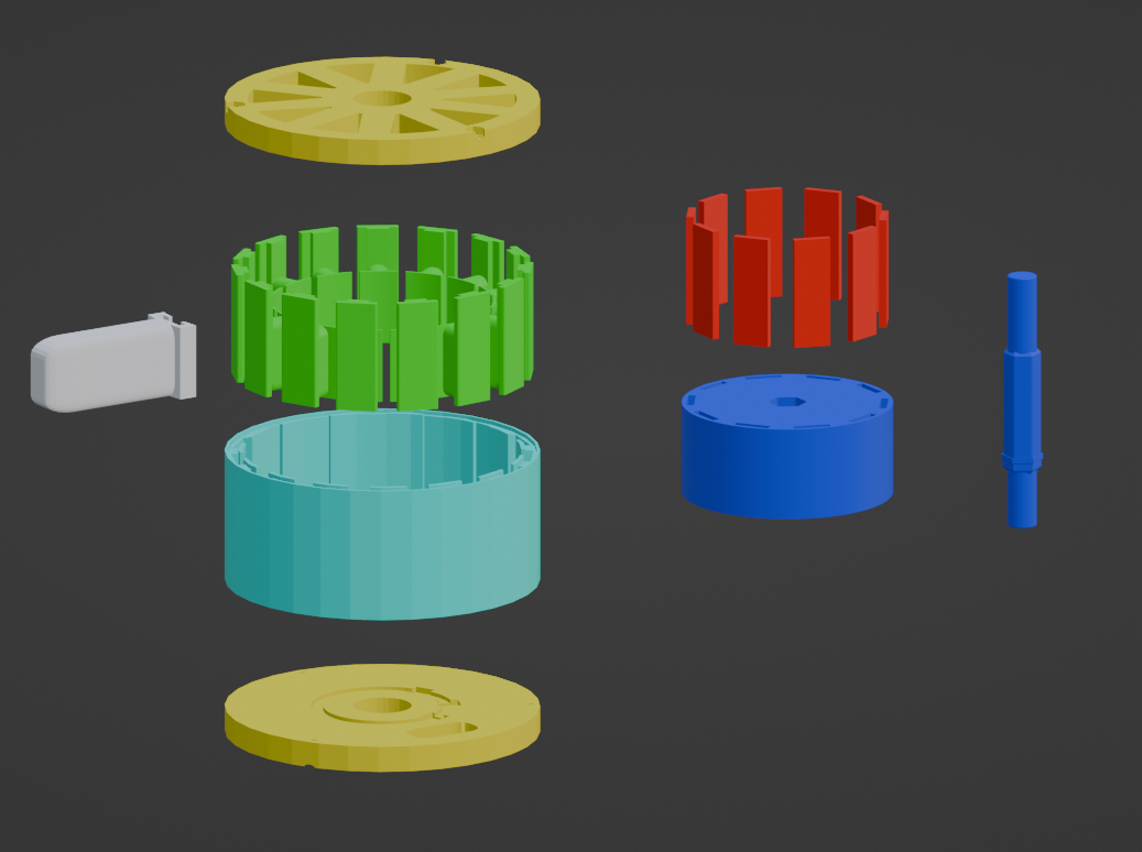
Design
In essence I need these components:
- Motor
- Magnets
- Enamelled copper wire
- Bearings
- Shaft
- Housing
- Hall effect sensors *
- Thermistors *
- Electronic Speed Controller
Hall effect sensorsMOSFETsCapacitorsResistorsDiodes
- MECHANICAL Speed Controller
- Small DC motor
- Throttle
- Mount for wire connections
- Arduino (or any other microcontroller) *
- Exotic slip ring (?)
- Gearbox
- Gears
- Bearings
- Housing
- Battery
- Li-ion cells
- Charger
* = Optional
Death to the ESC, long live MSC!
What I wrote while researching the ESC; The main problem I’m facing right now is the ESC design. It should have hall effect sensors but couldn’t find any for sale. I read that hobby-grade ESCs tend to try to spin the motor at a constant speed which would be really bad if I was trying to climb a hill. I’m pretty sure the coils would just melt. Not sure if I can control the PWM signal for the ESC from an Arduino and use the hall effect sensors to control the speed.
Now; Came across a video named “Brushless Motor Controller Without Electronics” which solves the problem of the ESC. TLDR; you can convert a brushless motor into a brushed motor by using a mechanical speed controller. You control the speed by controlling the voltage applied to the small motor. This means lower cost, efficiency and complexity. I would have to change the brushed motor every now and then but I think it’s worth it. I could design (or copy the design of) a ESC but the complexity and the cost of the components is too much for my taste right now. I can always come back and swap the mechanical speed controller with an electronic one.
Of course, I’m going to need to design a slip ring which can handle the current and the voltage. Even finding the name was challenging. Controlling a BLDC motor with a brushed DC motor requieres converting radial motion to act as a switch for each phase, if that makes sense.
Future me; Okay, constructing a custom commutator was a lot challenging than I thought. The small motor can’t overcome the friction of my “brushes”. The design was somewhat simple but had to be precise; a small motor rotates a disc that has one 120 degree sector which has bended copper wire on it. Cable mount holds the 3 phases of the motor and ensures that as the small motor spins, the copper wire makes contact with the phases.
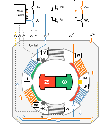
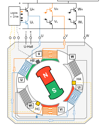
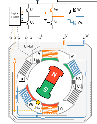
But you see, typically a BLDC motor has 3 phases and 2 of them are energized at any given time. Demonstration with a basic ESC;
 |
 |
 |
Energizing even one of the phases was challenging due to high friction so unfortunately I scrapped the idea but I will propably come back to it in the future. In the meantime I’ll use a standard, cheap ESC.
Windings
While I was researching the winding schemes, I came across this wonderful website which has a winding calculator. This should make the winding process much easier although I’m not sure about the “inrunner” part. I’ll have to do some more research on that.
Ideally I would like to have a winding scheme that has high symmetry because I don’t want the rotor pulling to one side. So a winding with 10 poles and 15 slots would be good, me thinks. It should look like this;
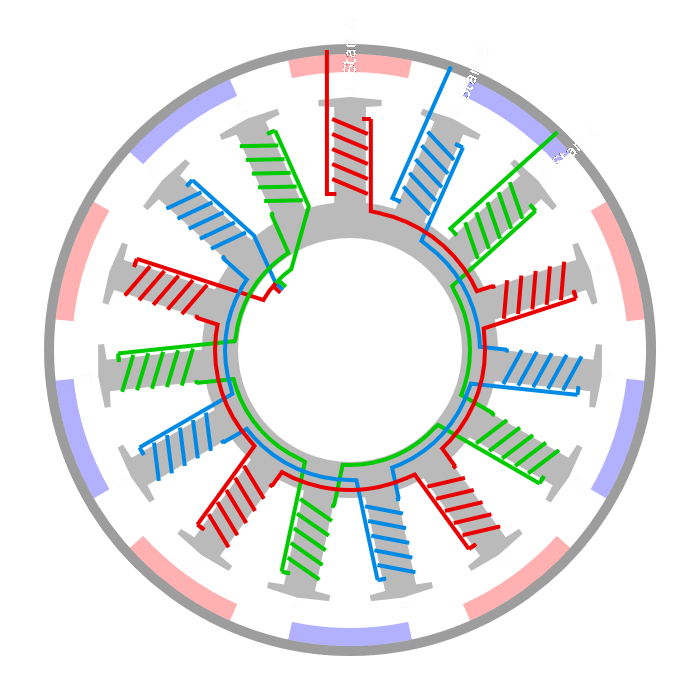
10 poles with 30x10x2 mm magnets. 15 slots with 0.5 mm wire. 110 liras (3.8$ as of 12/2023) for 10 magnets. 50 meters of 0.5 mm wire is approximately 180 liras (6.2$). With a quick and dirty calculation;
Coil dimension => 25x5x10 mm
One winding around one coil => 25mm + 5mm + 25mm + 5mm = 60mm = 6cm
1 full winding (1 layer of wire) =>  6cm * 40  = 2.4m
15 full windings => 2.4m * 15 = 36m
I’ve learned that the windings should be bigger than the magnets to prevent losses in axial flux motors/generators. I’m not sure if that’s correct. I made my windings smaller than the magnets. Should have tested it beforehand. :^)
The winding process is much more simpler if you choose a winding scheme that has a high symmetry. There’s no need to change the direction of the winding if you have a 10 pole, 15 slot motor, you just have to wind it in one direction and skip 2 slots while winding.
Also, I have to take into account the thickness of the wire. Wire gauge and temperature rise per ampere is a thing but on the bright side;
- The coils are powered 2 at a time, so one coil will be energized for 2/3 of the time.
- Again, the coils are powered 2 at a time, so the current will be split between 2 coils.
So if I have a 30 amp ESC and I use %100 of the power; 20 amps per 1 cycle, 20 amps per 2 coils, 10 amps per coil. I know 2/3 is a log of simplification but I think it’s a good enough approximation. We’ll see.
Magnets
Of course I cheated a little bit and take a look at the makeSEA brushledd motor design. They used 30x10x3 mm magnets and I got 30x10x2 mm magnets. Got them from Amazon but ofcourse they were %30 cheaper on the seller’s website. So I’m thinking buying 20 more magnets with different dimensions and either stacking them or implementing a halbach array.
Gearbox
Most of the foldable bikes use a 20 inch wheel so we’ll go with that.
inch to cm = 2.54
20 inch = 50.8 cm, radius = 25.4 cm
Circle circumference = 2 * pi * r = 1.596 m

Desired speed 20 km/h = 333.3 m/min
Needed RPM = 333.3 / 1.596 = 208.8 RPM
I could propably get a sprocket set with 40 teeth for the rear wheel and can print a 10 teeth sprocket for the motor. This would give me a 4:1 gear ratio. I reckon the ESC wouldn’t like a low RPM of 208*4 = 832, also the torque would be low too. This part is also “I’ll think about it later”. :^)
Battery
Battery is an entirely different beast. I’m thinking of using 18650 cells or a deep cycle, marine battery. I will think about it later. :^)
First Prototype
While constructing the first prototype, I dropped one of the magnets and it broke. Guess how many I needed and how many I ordered. :^)
I even designed a part to hold the individual coil mounts while I wind the coils. A coild mount mount.
I’ll update this section as I power the motor and test it.
Note to self; This entry was a bit rushed and unplanned. I’ll try to make next entries more structured and about a single topic.